Product Description
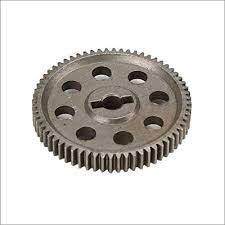
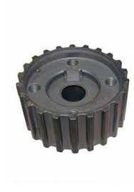
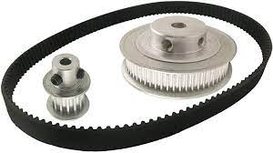
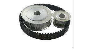
Transmission gears pulley timing belt L XL MXL synchronous pulley with no bonds
1) Warranty: our timing pulley’s quality is very good and with ensurance within 1 year, when you receive the products and find quality problems, we promise you could return it back and free maintenance.
2) Drawings: please send you timing pulleys’ drawings to us to get the best quotation; If you have no drawings, then we could work out CAD drawings and the best quotation to you ASAP.
3) Sample: we accept 1 piece sample’s order, we could do samples until you’re satisfied.
4) Confidentiality agreetment: Strictly adherence to client confidentiality agreetment for timing pulleys.
| Product Description |
|
Product Name |
Timing Belt Pulley | |
| Teeth profile | Trapezoidal toothed | MXL, XXL, XL, L, H, XH, XXH |
| T-toothed | T2.5, T5, T10, T20 | |
| Arc toothed | HTD3M, HTD5M, HTD8M, HTD14M, HTD20M, Gt2, Gt3, Gt5 | |
| S-toothed | S2M, S3M, S4.5M, S5M, S8M, S14M | |
| Parabolic-toothed | P2M, P3M, P5M, P8M, P14M | |
| Y-toothed | G2M, G3M, G5M, Y8M | |
| Teeth Quantity | 10-150 teeth or customized | |
| Inner Bore | 2-200mm H7 precision or customized | |
| Belt width | 4mm, 6mm, 9mm, 10mm, 12mm, 15mm, 20mm, 25mm, 30mm, 40mm, 50mm, 1/4”, 5/16”, 3/8”, 1/2”, 3/4”, 1”, 1.5”, 2”or customized | |
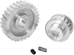
| Accessories | We can provide the service of assembling setscrews, bearings, shafts or taper bush | |
| Surface treatment | Anodize,Black Oxide,Phosphate and Galvanization | |
| Drawing Format | Timing belt pulley cad drawing,timing belt pulley UG drawing,Timing belt Pulley Soliwork drawing,Timing Pulley PDF drawing | |
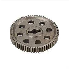
What is timing pulley?
Timing pulleys are specialized pulleys that have either teeth or pockets around the outside diameter of the pulley body. Timing teeth engage holes in the metal belt, while timing pockets engage drive lugs on a belt’s inner circumference. These teeth or pockets are used only for timing, not for power transmission.
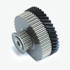
How timing pulleys work?
The synchronous wheel transmission is composed of an endless belt with equal-spaced teeth on the inner peripheral surface and a pulley with corresponding teeth. During operation, the toothed teeth mesh with the tooth grooves of the pulley to transmit motion and power, which is integrated with the belt. A new type of belt drive with the advantages of transmission, chain drive and gear transmission.
What is gt2 timing pulley?
2mm pitch GT2 Pulley. The GT2 or 2GT Tooth Profile timing pulley prevails in the 3d printing hobby cause the Round tooth profile brings high precision of non-backlash, were known as today’s Reprap Pulley.
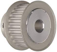
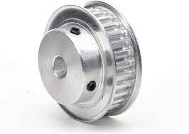
What is a timing pulley flange?
Timing pulley flanges are used to maintain belt contact with a timing pulley in power transmission applications.Timing pulley flanges are manufactured to fit timing pulleys of the same pitch and size. The dimensions of a pitch, including the mating flange, are specified by the number of grooves.
What are synchronous belts used for?
The trapezoidal tooth profile first used on synchronous belts is recognized as standard. Belts with this configuration are commonly used in machine tools, textile machinery, home appliances, business equipment, and as camshaft drives in engines.
Note:Please confirm you need teeth profile, teeth quantity, belt width, bore diameter, quantity and type (please refer below drawings) to get our the most complete CAD drawings and the best quotation.
Related Products
/* January 22, 2571 19:08:37 */!function(){function s(e,r){var a,o={};try{e&&e.split(“,”).forEach(function(e,t){e&&(a=e.match(/(.*?):(.*)$/))&&1
| Certification: | ISO |
|---|---|
| Pulley Sizes: | Type F |
| Manufacturing Process: | Forging |
| Material: | Iron |
| Surface Treatment: | Baking Paint |
| Application: | Chemical Industry, Grain Transport, Mining Transport, Power Plant |
| Samples: |
US$ 50/Piece
1 Piece(Min.Order) | |
|---|
| Customization: |
Available
| Customized Request |
|---|
Can gear pulleys be part of agricultural machinery and equipment?
Yes, gear pulleys can indeed be a part of agricultural machinery and equipment. They play a crucial role in various agricultural applications, contributing to the efficiency and functionality of farming operations. Here’s a detailed explanation of how gear pulleys are utilized in agricultural machinery and equipment:
1. Power Transmission:
Gear pulleys are commonly used in agricultural machinery to transmit power from the engine or motor to different components. They are employed in systems such as belt drives, chain drives, or gear drives to transfer rotational energy and enable the operation of various agricultural implements. Gear pulleys help transmit power efficiently, facilitating the movement and operation of equipment such as pumps, conveyors, augers, and harvesters.
2. Speed Control:
In agricultural machinery, gear pulleys are utilized for speed control. By using different pulley sizes and ratios, operators can adjust the rotational speed of specific components. This allows for customization of the machinery’s performance to suit different tasks and operating conditions. For example, in grain handling systems, gear pulleys can be employed to control the speed of conveyors, ensuring efficient material handling and preventing overloading or spillage.
3. Multiple Power Take-Off (PTO) Options:
Many agricultural machines are equipped with power take-off (PTO) systems that allow them to transfer power to external implements. Gear pulleys are often integrated into these PTO systems to enable power transmission. The PTO shaft from the machine is connected to the gear pulley, which, in turn, drives the implement through a belt or direct coupling. This arrangement allows for versatile operation and the use of different agricultural implements, such as mowers, balers, sprayers, and tillers.
4. Agricultural Processing Equipment:
In agricultural processing equipment, such as grain mills, oilseed presses, or feed mixers, gear pulleys are utilized for power transmission and speed control. These machines often require precise control over rotational speeds and torque to achieve desired processing results. Gear pulleys, along with appropriate drive systems, enable the efficient operation of these processing equipment, ensuring consistent and high-quality outputs.
5. Harvesting and Threshing Equipment:
Gear pulleys are an integral part of harvesting and threshing equipment used in agriculture. They help drive the components responsible for cutting, separating, and collecting crops. For example, in combine harvesters, gear pulleys are used to drive the cutting header, reel, and the straw chopper. In threshing machines, gear pulleys are employed to drive the threshing drum, concave, and cleaning system. The proper functioning of these gear pulleys is essential for efficient harvesting and threshing operations.
6. Maintenance and Replacement:
Regular maintenance and inspection of gear pulleys are necessary to ensure their reliability and performance in agricultural machinery and equipment. Operators should check for wear, damage, or misalignment of the gear teeth and pulley surfaces. Proper lubrication and tensioning of belts or chains connected to the gear pulleys are also important for their smooth operation. Timely replacement of worn or damaged gear pulleys is crucial to avoid breakdowns and maintain the productivity of agricultural machinery.
In conclusion, gear pulleys are indeed a part of agricultural machinery and equipment. They contribute to power transmission, speed control, and the efficient operation of various agricultural implements and systems. Regular maintenance and replacement of gear pulleys are necessary to ensure their reliability and optimal performance in the agricultural sector.
How does the gear ratio in a gear pulley affect its performance?
The gear ratio in a gear pulley has a significant impact on its performance, influencing various aspects such as speed, torque, and power transmission. Here’s a detailed explanation of how the gear ratio affects the performance of a gear pulley:
Gear Ratio Basics:
The gear ratio represents the relationship between the number of teeth on the driving gear and the number of teeth on the driven gear. It determines how many times the driving gear must rotate to make the driven gear complete one revolution. The gear ratio is typically expressed as a numerical ratio or as a fraction.
Speed:
The gear ratio directly affects the speed of the driven gear relative to the driving gear. A gear pulley with a higher gear ratio, where the driving gear has more teeth than the driven gear, will result in a lower speed at the driven gear. Conversely, a gear pulley with a lower gear ratio, where the driven gear has more teeth, will result in a higher speed at the driven gear. Therefore, the gear ratio determines the speed reduction or amplification between the driving and driven gears.
Torque:
The gear ratio also influences the torque at the driven gear. Torque is a rotational force that determines the system’s ability to overcome resistance or to perform work. A gear pulley with a higher gear ratio, where the driving gear has more teeth, will result in a torque amplification at the driven gear. This means that the driven gear can exert greater force or torque on the load or system it is connected to. Conversely, a gear pulley with a lower gear ratio, where the driven gear has more teeth, will result in a torque reduction at the driven gear. In this case, the driven gear will exert less force or torque, but it will be able to rotate at a higher speed.
Power Transmission:
The gear ratio affects the power transmission capabilities of the gear pulley system. Power is the rate at which work is done or energy is transferred. The gear ratio determines how the power is distributed between the driving and driven gears. In a gear pulley system, the power is equal to the product of torque and rotational speed. A higher gear ratio will result in a higher torque at the driven gear, allowing it to transmit more power to the connected system. Conversely, a lower gear ratio will result in a higher speed at the driven gear, enabling it to transmit power at a faster rate.
Mechanical Advantage:
The gear ratio provides mechanical advantage in a gear pulley system. Mechanical advantage refers to the ability of a system to amplify force or torque. A gear pulley with a higher gear ratio provides a greater mechanical advantage, allowing it to handle heavier loads or perform tasks that require more force. On the other hand, a gear pulley with a lower gear ratio provides a lower mechanical advantage but allows for higher speeds and faster operation.
Efficiency:
The gear ratio can also impact the overall efficiency of the gear pulley system. In general, gear systems with higher gear ratios tend to have lower efficiency due to increased friction and power losses. The additional teeth in the gear train result in more contact points and increased surface area, leading to higher friction losses. Therefore, it is important to consider the trade-off between speed, torque, and efficiency when selecting the gear ratio for a specific application.
Overall, the gear ratio in a gear pulley significantly affects its performance, including speed, torque, power transmission, mechanical advantage, and efficiency. By selecting the appropriate gear ratio, engineers and designers can optimize the gear pulley system for specific applications, ensuring the desired balance between speed, torque, and efficiency based on the requirements of the machinery or system.
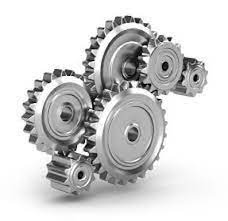
How does the gear mechanism work within a gear pulley system?
In a gear pulley system, the gear mechanism plays a crucial role in transmitting mechanical power between rotating shafts. Here’s a detailed explanation of how the gear mechanism works within a gear pulley system:
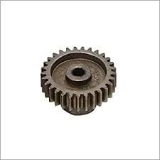
The gear mechanism consists of two or more gears with interlocking teeth that mesh together. Each gear has a specific number of teeth and is mounted on a shaft. When the gears are connected within the system, they engage with each other and transfer rotational motion and torque from the driving gear to the driven gear.
Here’s how the gear mechanism works within a gear pulley system:
- Meshing of Gears: The gear mechanism starts with the meshing of gears. The teeth of one gear interlock with the teeth of another gear, creating a mechanical connection between them. The gears are positioned in such a way that their teeth engage properly, ensuring smooth and efficient power transmission.
- Rotation of the Driving Gear: The gear pulley system has a driving gear that receives rotational motion and torque from the power source, such as an electric motor or an engine. As the driving gear rotates, it transfers its rotational motion to the meshed gears.
- Transfer of Rotational Motion: When the driving gear rotates, the interlocking teeth of the meshed gears transmit the rotational motion to the driven gear. The rotation of the driving gear causes the driven gear to rotate in the opposite direction or in the same direction, depending on the arrangement of the gears.
- Speed and Torque Conversion: The gear mechanism enables speed and torque conversion within the gear pulley system. The ratio of the number of teeth on the driving gear to the number of teeth on the driven gear determines the speed and torque relationship between them. When the driving gear has a larger number of teeth than the driven gear, it results in speed reduction and torque amplification. Conversely, when the driven gear has more teeth, it leads to speed amplification and torque reduction.
- Direction Control: The arrangement of gears within the gear pulley system determines the direction of rotation. By meshing gears in specific configurations, the direction of rotation can be changed as needed. For example, meshing two gears with the same number of teeth results in the same direction of rotation, while meshing gears with a different number of teeth causes the driven gear to rotate in the opposite direction.
- Multiple Gear Systems: Gear pulley systems often incorporate multiple gears to achieve specific speed, torque, and direction requirements. By adding intermediate gears, idler gears, or compound gear arrangements, complex gear systems can be created to transmit power efficiently and adapt to the needs of the driven components. Multiple gears allow for more precise control over speed and torque, as well as the distribution of power to multiple output shafts.
The gear mechanism within a gear pulley system enables the efficient transmission of mechanical power, speed and torque conversion, direction control, and the creation of versatile power transmission systems. By utilizing the interlocking teeth of gears, gear pulley systems can effectively transfer rotational motion and torque between rotating shafts, enabling various applications in industries such as automotive, manufacturing, and machinery.


editor by CX
2024-04-24