Product Description
Stone/Rock/Mining Crusher Spare Parts Jaw/Cone/Impact/VSI Crusher Parts
We provide crusher spare parts for many band of crushing plants.
We provide replacement parts for many brands of crushing plants. like, manganese liners,cone crusher mantle and concave(bowl liner), hsi bars and liners, blow bars, side liners, jaw liners, jaw plates, teeth plates, VSI wear parts, etc, for jaw crusher, cone crusher, impact crusher, VSI sand maker, etc.
We can provide custom casting service, based on the drawings from the clients.
We will make wooden mould, and sand cast the parts, after a series processes, you will get high quality wear parts in high manganese matching your machines.
1-Introduction of Jaw Crusher Parts
Jaw plate is manufactured with super high manganese steel, therefore it has a service life 50~100% longer than those made of traditional high manganese steel. Every model of PE series jaw crushers is tested for shock, stress, strain, thermal loading, deformation, vibration and noise under a wide range of load conditions. The special processing techniques ensure that our jaw plate has leading performance:
1)Using cold processing hardening technology, the hardness is improved.
2)Water toughening technology to avoid making the performance poor during the process of natural phase change.
2- Introduction of Cone Crusher Parts
which is designed to protect the Cone Crusher, thus improves the working life.We supply high qualified concave in high Cr, Mo, alloy steel for Cone Crusher.
Cone Crusher Parts
1. Spare parts for Cone Crusher.
2. Be used in manganese steel
3. We can do as per customer’s requirements.
We manufacture an extensive range of wear and spare parts in China for the worlds most popular crushing brands, like the spare parts for the below crushers.
| Crusher type | Model | Spare parts |
| Cone crusher | HP100, HP200, HP300, HP400, HP500, HP4, HP5, GP100, GP200, GP300, GP550, GP11 | Bowl liner, mantle |
| H2800, H3800, H4800, H6800, H7800, H8800, S2800, S3800, S4800, S6800 | ||
| 4FT.Standard, 4-1/4FT.Short head , 5-1/2FT.Standard |
Features of cone crusher wear parts :
1) Material: high manganese steel:Mn13Cr2, Mn18Cr2, etc;
2) Use: Machinery in metal recovery smash, mine, metallurgy, chemical industry, cement, petroleum etc.
3) Production quality testing: High frequency infrared carbon & sulfur analyzer, Metallographic microscope, Machinery performance testing equipment, Hardness testing equipment, Ultrasonic inspection equipment
4) Easy installation: The anti-abrasion block is a semi-permanent part, which is easy for replacement.
Chemical composition of cone crusher wear parts
| Code Elem | C | Mn | Si | Cr | Mo | P | S |
| ZGMn13-1 | 1-1.45 | 11-14 | 0.3-1 | – | – | ≤0.09 | ≤0.04 |
| ZGMn13-2 | 0.9-1.35 | 11-14 | 0.3-1 | – | – | ≤0.09 | ≤0.04 |
| ZGMn13-3 | 0.9-1.35 | 11-14 | 0.3-0.8 | – | – | ≤0.09 | ≤0.04 |
| ZGMn13-4 | 0.9-1.3 | 11-14 | 0.3-0.8 | 1.5-2 | – | ≤0.09 | ≤0.04 |
| ZGMn13-5 | 0.75-1.3 | 11-14 | 0.3-1 | – | 0.9-1.2 | ≤0.09 | ≤0.04 |
3-Introduction of Impact Crusher Parts
Blow bar Made by high wear-resisting material:high chrome cast-iron and high-manganese steel.
We manufacture an extensive range of wear and spare parts in China for the worlds most popular crushing brands.
Chemical composition of Impact Crusher Parts
| NO. | chemical composition % | HRC | ||||||||
| C | Si | Mn | Cr | Mo | Na | Cu | P | S | ||
| KmTBCr4Mo | 2.5-3.5 | 0.5-1.0 | 0.5-1.0 | 3.5-4.5 | 0.3-0.5 | – | – | ≤0.15 | ≤0.10 | ≥55 |
| KmTBCr9Ni5Si2 | 2.5-3.6 | 1.5-2.2 | 0.3-0.8 | 8.0-10.0 | 0-1.0 | 4.5-6.5 | 4.5-6.5 | – | – | ≥58 |
| KmTBCr15Mo | 2.8-3.5 | ≤1.0 | 0.5-1.0 | 13-18 | 0.5-3.0 | 0-1.0 | 0-1.0 | ≤0.10 | ≤0.06 | ≥58 |
| KmTBCr20Mo | 2.0-3.3 | ≤1.2 | ≤2.0 | 18-23 | ≤3.0 | ≤2.5 | ≤1.2 | – | – | ≥60 |
| KmTBCr26 | 2.3-3.3 | ≤1.2 | ≤1.0 | 23-30 | ≤3.0 | ≤2.5 | ≤2.0 | – | – | ≥60 |
Crusher Wear Parts
/* January 22, 2571 19:08:37 */!function(){function s(e,r){var a,o={};try{e&&e.split(“,”).forEach(function(e,t){e&&(a=e.match(/(.*?):(.*)$/))&&1
| After-sales Service: | One Year |
|---|---|
| Warranty: | One Year |
| Certification: | ISO 9001:2008 |
| Standard: | AISI, GB, ASTM, DIN |
| Surface Treatment: | Without Processing |
| Manufacturing Process: | Casting |
| Samples: |
US$ 200/Piece
1 Piece(Min.Order) | |
|---|
| Customization: |
Available
| Customized Request |
|---|
What maintenance procedures are necessary to ensure the reliability of gear pulleys?
Proper maintenance procedures are crucial for ensuring the reliability and longevity of gear pulleys. Here are some essential maintenance steps to consider:
- Regular Inspection: Conduct routine inspections of the gear pulleys to check for any signs of wear, damage, or misalignment. Inspect the gear teeth, pulley surfaces, and the overall condition of the pulley assembly. Look for any cracks, chips, or excessive wear that may affect the pulley’s performance.
- Lubrication: Ensure that the gear pulleys are adequately lubricated. Lubrication helps reduce friction and wear between the gear teeth and the pulley surfaces. Follow the manufacturer’s recommendations for the appropriate lubricant type and schedule. Apply lubrication as specified to maintain smooth operation and prevent premature failure.
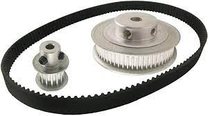
- Tension Adjustment: Check the tension of the belt connected to the gear pulleys. Proper tension is essential for efficient power transmission and to prevent slippage. If the belt is too loose or too tight, adjust the tension according to the manufacturer’s guidelines. Use tensioning devices such as idler pulleys or tensioners to achieve the optimal tension.
- Alignment: Ensure that the gear pulleys are properly aligned. Misalignment can lead to excessive wear, noise, and reduced efficiency. Use alignment tools and techniques to align the pulleys accurately. Check the alignment periodically and make any necessary adjustments to maintain proper alignment.
- Cleaning: Keep the gear pulleys clean and free from dirt, debris, and contaminants. Regularly clean the pulley surfaces using a suitable cleaning method recommended by the manufacturer. This helps prevent abrasive particles from damaging the gear teeth and ensures smooth operation.
- Replacement: If any significant wear, damage, or defects are observed during inspection, consider replacing the gear pulleys promptly. Delaying the replacement can result in further damage to the pulleys and other system components. Follow the manufacturer’s guidelines and specifications for selecting and installing the appropriate replacement pulleys.
- Professional Maintenance: In complex HVAC systems or air conditioning units, it is often advisable to seek professional maintenance services. HVAC technicians or qualified professionals can perform comprehensive inspections, maintenance, and repairs on gear pulleys and associated components.
By following these maintenance procedures, you can ensure the reliability and optimal performance of gear pulleys in HVAC systems and air conditioning units. Regular inspections, lubrication, tension adjustment, alignment checks, cleaning, and timely replacement contribute to the longevity and efficiency of gear pulleys, minimizing the risk of unexpected failures and system downtime.
What role do gear pulleys play in automotive engines and accessory systems?
Gear pulleys play a crucial role in automotive engines and accessory systems, contributing to the overall functionality and performance of vehicles. Here’s a detailed explanation of the role gear pulleys play in automotive engines and accessory systems:
Engine Timing:
One of the primary roles of gear pulleys in automotive engines is to control the engine timing. The timing belt or chain, which is driven by the crankshaft gear pulley, connects to the camshaft gear pulley. This synchronization between the crankshaft and camshaft ensures that the engine’s valves open and close at the correct time in relation to the piston’s position. Proper engine timing is essential for efficient combustion, optimal power delivery, and prevention of engine damage.
Accessory Drive Systems:
Gear pulleys are also integral components of accessory drive systems in automotive engines. These systems transmit mechanical power from the engine to various accessories such as the alternator, water pump, power steering pump, and air conditioning compressor. The accessory drive belt, often referred to as the serpentine belt, wraps around multiple gear pulleys and transfers rotational motion from the crankshaft pulley to the accessory pulleys. Gear pulleys in the accessory drive system ensure that the accessories operate smoothly and efficiently, providing electrical power, cooling, steering assistance, and climate control to the vehicle.
Supercharging and Turbocharging:
Gear pulleys are commonly used in supercharging and turbocharging systems to increase the engine’s power output. Superchargers and turbochargers are devices that compress the incoming air to deliver more oxygen to the engine, resulting in improved combustion and increased horsepower. Gear pulleys are utilized in the drive systems of these devices to transfer power from the engine to the supercharger or turbocharger. By driving the compressor with a gear pulley system, the intake air pressure is boosted, providing enhanced engine performance.
Variable Valve Timing:
Some modern automotive engines incorporate variable valve timing (VVT) systems to optimize engine performance at different engine speeds and loads. Gear pulleys are essential components of these systems. VVT systems use hydraulic actuators or electronic controls to adjust the position of the camshaft gear pulley relative to the crankshaft gear pulley. This adjustment alters the timing of the intake and exhaust valves, optimizing valve opening and closing events for improved fuel efficiency, power delivery, and emissions control.
Engine Balancing:
In certain engine designs, gear pulleys are utilized to balance the engine’s rotating assembly and reduce vibrations. Balancing gear pulleys can be mounted on the crankshaft to counteract the inherent imbalance caused by the reciprocating motion of the pistons. These balancing pulleys help minimize engine vibrations, leading to smoother operation, reduced noise, and improved overall engine longevity.
The role of gear pulleys in automotive engines and accessory systems is crucial for achieving proper engine timing, driving accessory components, enhancing engine performance through forced induction, optimizing valve timing, and reducing vibrations. By effectively transmitting power and enabling precise control over various engine functions, gear pulleys contribute significantly to the reliable operation and performance of automotive engines and accessory systems.
How does the gear mechanism work within a gear pulley system?
In a gear pulley system, the gear mechanism plays a crucial role in transmitting mechanical power between rotating shafts. Here’s a detailed explanation of how the gear mechanism works within a gear pulley system:
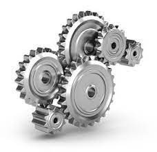
The gear mechanism consists of two or more gears with interlocking teeth that mesh together. Each gear has a specific number of teeth and is mounted on a shaft. When the gears are connected within the system, they engage with each other and transfer rotational motion and torque from the driving gear to the driven gear.
Here’s how the gear mechanism works within a gear pulley system:
- Meshing of Gears: The gear mechanism starts with the meshing of gears. The teeth of one gear interlock with the teeth of another gear, creating a mechanical connection between them. The gears are positioned in such a way that their teeth engage properly, ensuring smooth and efficient power transmission.
- Rotation of the Driving Gear: The gear pulley system has a driving gear that receives rotational motion and torque from the power source, such as an electric motor or an engine. As the driving gear rotates, it transfers its rotational motion to the meshed gears.
- Transfer of Rotational Motion: When the driving gear rotates, the interlocking teeth of the meshed gears transmit the rotational motion to the driven gear. The rotation of the driving gear causes the driven gear to rotate in the opposite direction or in the same direction, depending on the arrangement of the gears.
- Speed and Torque Conversion: The gear mechanism enables speed and torque conversion within the gear pulley system. The ratio of the number of teeth on the driving gear to the number of teeth on the driven gear determines the speed and torque relationship between them. When the driving gear has a larger number of teeth than the driven gear, it results in speed reduction and torque amplification. Conversely, when the driven gear has more teeth, it leads to speed amplification and torque reduction.
- Direction Control: The arrangement of gears within the gear pulley system determines the direction of rotation. By meshing gears in specific configurations, the direction of rotation can be changed as needed. For example, meshing two gears with the same number of teeth results in the same direction of rotation, while meshing gears with a different number of teeth causes the driven gear to rotate in the opposite direction.
- Multiple Gear Systems: Gear pulley systems often incorporate multiple gears to achieve specific speed, torque, and direction requirements. By adding intermediate gears, idler gears, or compound gear arrangements, complex gear systems can be created to transmit power efficiently and adapt to the needs of the driven components. Multiple gears allow for more precise control over speed and torque, as well as the distribution of power to multiple output shafts.
The gear mechanism within a gear pulley system enables the efficient transmission of mechanical power, speed and torque conversion, direction control, and the creation of versatile power transmission systems. By utilizing the interlocking teeth of gears, gear pulley systems can effectively transfer rotational motion and torque between rotating shafts, enabling various applications in industries such as automotive, manufacturing, and machinery.


editor by CX
2024-05-02